
High Voltage Output Hi-Power Supply Application
By: Willard Wu/ Technical Dept.
willard@meanwell.com
In the past, power supplies complied with SELV with low voltage output are commonly used, such as 3.3V/5V/12V output for ATX power supply, 19V~24V adapters for lab top and 12V/24V/48V for industrial power supply. However, nowadays, the demand for high voltage output applications are growing gradually, in the fields such as UV curing equipment and laser apparatus.
Numbers of power supplies were connected to achieve high voltage output (Figure 1.)when there was no suitable high voltage output power supply. Extra diodes are required to prevent damage during cold start. Not only does the cost go up, but also failure rate and complexity are increased. Undoubtedly, CSP-3000 series is the perfect models for overcoming these issues.
.png) |
| Figure 1. Power supplies connected to achieve high voltage output |
CSP-3000 is a 3kW AC/DC single output power supply with input range from 180~264Vac, providing high voltage DC output needed the most in the market. CSP-3000 is capable to operate under ambient temperature up to 70℃(Please refer to derating curve) with forced fan cooling topology. Moreover, CSP-3000 is build-in with multiple features, such as PV/PC, parallel, remote on/off and aux winding, which highly increases the flexibility of usage.
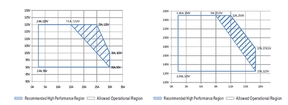
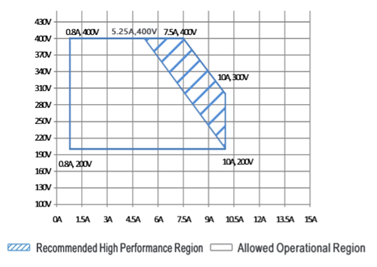
To apply CSP-3000 series in LED application, operating under the blue operating region from figure 2 ~ figure 4 is recommended, where to ensure the best performance of CSP-3000.
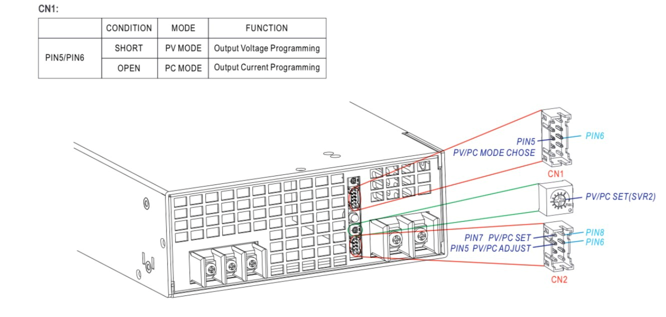
Output voltage and output current can be adjusted through PV/PC function. Either PV or PC function can be activated through PIN5/PIN6 on CN1. If Pin5/Pin6 is shorted, PV function is activated, vice versa, PC function is activated.
 |
||
| Figure 2. CSP-3000-120 | Figure 3. CSP-3000-250 | |
 |
||
| Figure 4. CSP-3000-400 | ||
 |
||
| Figure 5. PV/PC Mode and Pin Function Mechanism | ||
 |
||
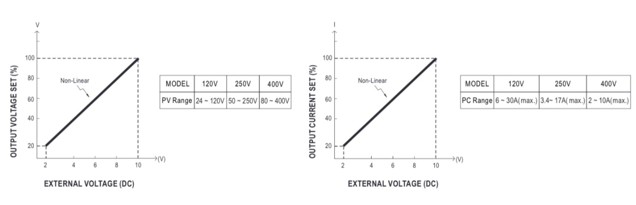
| Figure 6. Vo-Vs Chart | Figure 7. Io-Vs Chart | |
 |
||
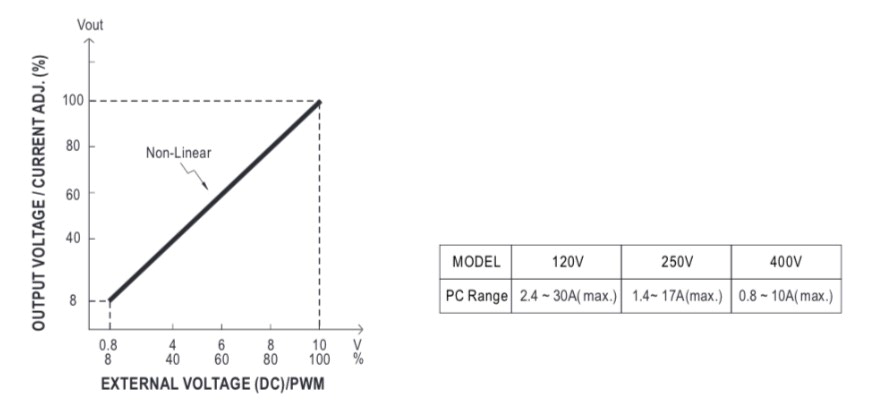
| Figure 8. Vo/Io-Vs Chart | ||
There are three ways to adjust output voltage under PV function mode. 1st method is using SVR2 to adjust output voltage within the adjustment range from 20% ~ 100%. 2nd is by applying a DC voltage signal Vs between PIN7/PIN8 within the adjustment range from 20% ~ 100%(shown as figure 6) when Vs < 2V, Vo ≧ 10% of the rate voltage. 3rd is by applying a DC signal Vs between PIN5/PIN6, with wider adjustment range from 8% ~ 100%, and also perform better during dynamic situation. Please refer to figure 8 for reference.
Under PC mode, SVR2 is used to set the maximum constant current protection point Imax. There are 2 ways to adjust the output current Io, 1st one is to adjust through CN2 by applying a DC voltage signal Vs on PIN7/PIN8, and posses adjustment range from 20% ~100% (shown as figure 7). 2nd is by apply a DC signal Vs between PIN5/PIN6, with wider adjustment range from 8% ~ 100%, and perform better during dynamic situation also. Please refer to figure 8 for reference.
For a better understanding, please refer to the following video.