
MEAN WELL's power supplies have been used in a wide variety of electronic equipments, including factory control, IT, communication, appliances, medical, lighting, billboards, security, vehicle, etc…., which is capable of meeting your needs.
Application Aspect
Points on connecting wires used in power supplies?
To install a power supply into the system, you would need wires for the connection both to the loads and to the energy source. There are a couple of points that should be taken into consideration when choosing wires, one is current rating, it may cause high heat on the wires or burnt out in the worst case, if the rating is not enough. The other is voltage drop, there would be voltage reduction at load side as current moves through the wires owing to the internal resistance. If too much voltage drop in line, there could be no sufficient voltage to drive the loads. You can find the right wires for use by referring to the table below on the basis of your system design.

How to select adaptors with the correct AC plug for use in different countries?
An adaptor may need connection of a power cord to receive energy needed from the utility. You can refer to the specification of the adaptor for the connector (AC inlet) at the adaptor end of the power cord; Different countries/regions vary in type of AC socket and voltage, please look at the table below for the information of the AC plug you need.


A few things you should know before using the Remote Sensing function
First, use twisted wires, connect +S to the positive end of the output, then -S to the negative end of the output, as shown in the illustration. Also, keep the wires off the AC and output cables to prevent noise interference.
Add capacitors at output end where the Remote Sensing wires are connected to if dynamic load (frequency above 1K Hz) is used. The purpose is to reduce noise as Remote Sensing is a sensitive function. A suitable capacitor requires two factors:
a. Rated Ripple Current is 0.2 times greater than the output current
b. Rated Voltage is higher than the output voltage

Is it possible to build your own charging curve on the smart chargers when the pre-defined charging curves do not satisfy battery charging requirements?(Video tutorial Inside)
Yes, charging curves of smart chargers including ENC series, RPB series and RCB series can be set and adjusted through SBP-001, the charging programmer.
SBP-001 utilizes the software with the connection between the charger and itself to allow users to programme charging curves.
Adjustable functions are:
Charging parameter adjustment: Values of constant current (CC), constant voltage (CV), float voltage (FV) and tapper current (TC) can be set and adjusted.
Battery temperature compensation: Various charging voltage compensation is provided for battery at different temperature conditions.
Timeout setting: Fully programmable timeout during stages enables to be set to shutdown the charger to prevent battery over-charge.
Please refer to the user’s manual as link below for detailed information:
https://www.meanwell.com/webapp/product/search.aspx?prod=SBP-001
Following video is an example of demonstrating the ENC-120.
What should we pay attention to if system implemented magnetic component?
Nowadays, customer implement magnetic component in their system to achieve fast installation and maintenance. The magnetic component should keep as far as possible from PSU to avoid interference in the control circuitry of PSU. If limitation of distance is unavoidable, install a well magnetic-conducted metal plate (ex: steel plate, copper plate) between PSU and magnetic component to minimize the interference.
How to choose a suitable power supply for a charging application?
MEAN WELL has launched ENC, HEP-600C, GC, PA, PB, RPB and RCB series for battery charge applications (30~360W). However, if these models still cannot fulfill customer’s requirements, there is an alternative for the purpose. Power supplies with constant current limiting as overload protection are suggested. Charge current varies in battery percentage (full or flat), there is high possibility to trigger overload protection when battery is low, those with overload protection as hiccup or shutdown will stop charging the battery in low battery condition. Yet, using a power supply as charging purpose is considered as over load usage, modification is required. Please contact MEAN WELL for the request.
What are the applications with serial connection?
There are two different applications when PSU are connected in series. One is to generate plus minus voltage, another is to increase total output voltage. Connection methods are as follows:
(1) Connection for plus and minus voltage are shown as follow

(2) To increase the total output voltage (Output current remain the same). Diode connect in parallel at output
side of the driver is necessary to prevent damage during start up. The voltage rating of diode shall greater
than V1 + V2( shown as figure below), in addition, peak forward surge current rating shall greater than
rated current.

* Because part of the signal ground is shorted with output ground, strongly suggest to use isolated signals to
achieve control scheme, in order to prevent damage to the product.
What are the requirements of parallel connections? What are the differences between parallel and redundant.
When power supplies are connected in parallel, mostly, is intent to increase the output current. Due to the design of active current sharing, they are mostly without reverse current protection, therefore, they are not the best solution when talking about redundancy. For redundant purpose, please choose the PSU with redundant function or implement external redundant modules. Be sure that the difference in output voltage and wiring impedance, should be as small as possible.
1. Use PSP models as example, connect P(LP/CS) terminals together (Please refer to the parallel function of
specification). Input and output should be connected in parallel before connecting to the AC source and
loads. Shown as in picture below (some S.P.S. require a minimum load after paralleling).

2. Output voltage difference between S.P.S. units should be as small as possible, normally < 0.2V.
3. The power supplies should be paralleled with short and large diameter wiring together first, and then
connected to the load.
4. After paralleling, the maximum usage of total power should be around 90% of the rated total power.
5. When power supplies are paralleled, if the load is lower than 10% of rated load of individual S.P.S. The LED
indicator or signals (Power Good、Pok、Alarm Signal) may malfunction.
6. To ensure that the load current is effectively shared in parallel operation, in general, it is recommended not to
use more than 4-6 power supplies at one time.
7. In some models, the +S, -S terminals should be used to reduce unstable pulsation of output voltage.
Why I can not turn on the power supply smoothly when the loads are motors, light bulbs or capacitive loads?
If you connect the S.P.S. to motors, light bulbs, or high capacitive loads, you will have a high output surge current when you turn on the S.P.S. and this high surge current will cause failure of start up. We suggest using S.P.S. with constant current limiting protection to deal with these loads.
The output ground (GND) and frame ground (FG) is the same point in my system, can MEAN WELL's power supplies be used in such system?
Yes. Since our products are designed based on isolation concept, it will be no problem that the output ground (GND) and frame ground (FG) is the same point in your system. But, EMI may be affect by this connection.
When using MEAN WELL products, voltage is found on the outer case, is it normal?
Due to the requirement of EMI, capacitors are connected to FG(Case) for filtering, leading voltage encounter on the case. This effect is clearly state in IEC62368-1 regulation, such as equipment for IT application, <2mA is necessary, and it can be solved by proper grounding connection.
For certain need, is it possible to reduce the noise of fan?
Noise is directly related to the fan which is build into the power supply. Lowering the airflow of the fan means reducing the heat dissipation ability. It will also influence the reliability of the products. Furthermore, minimum airflow of fans is defined by Safety Organization and a safety appendage will be needed if using a new fan. If fan noise is a critical concern, we suggest to select FANLESS products or contact MEAN WELL for other possibilities according to the conditions of use.
What should be noticed when installing a power supply in vertical and horizontal directions?
Most small wattage and fanless power supplies are mainly installed in the horizontal position. If you have to install it vertically because of mechanical limitation, you should consider the output derating due to the heat concern. The temperature derating curve can be found on the spec sheet. Regarding the power supplies with built-in fan or the application has forced cooling system, vertical and horizontal installations have less difference. Ex. In SP-150 derating curve, the ambient temperature difference in application is 5 Celsius from vertical to horizontal. The output wattage in forced cooling can be 20% higher than air cooling convection.
Can MEAN WELL charger use on lithium or other types of batteries?
All MEAN WELL chargers are preset for lead-acid batteries. For other products that can customize the charging curve (such as ENC / NPB series), customers can customize their charging curve depending on the charging and discharging characteristics of batteries. If you have other requirements, please contact MEAN WELL distributor.
Does the power supply capable to operates at high altitude condition.
The limitation for MEAN WELL power to operate under high altitude are as follow:
1. Operating temperature should decrease every 3.5℃/1000m for fan-less power supplies.
2. Operating temperature should decrease every 5℃/1000m for power supplies with fan.
*Should there be any concern about safety insulation, please contact our sales representatives
Can I use BIC-2200 as an ordinary stand-alone inverter like NTS/NTU/TN series?
No. The BIC-2200 is designed with grid-tie compatible, meaning that the BIC-2200 will enter anti-islanding protection and not generate any AC energy when disconnect the bidirectional power supply from the mains. Therefore, the BIC-2200 could not be used as an ordinary stand-alone inverter.
Why I cannot use battery mode and C/D control function in BIC-2200?
Battery mode and C/D control function only can be activated via CANBus communication interface. If you do need these functions, please contact our distributor and order BIC-2200CAN.
How to select a MCB with S.P.S.?
A: Steps
- Check for the circuit breaker information in specification or installation. If it is not shown, you can calculate it according to the following steps.
- Enter MEAN WELL Expo with following LINK. https://expo.meanwell.com/cbs/index.html
- Fill in the values of inrush current , T50(Note 3) and Rated AC current that is defined in the specification accordingly.
- The result must be verified onsite.
B: Calculation demonstration
Taking HLG-600H as an example, the inrush current is 70A, the T50 is 1000us, and the AC current under 230VAC is 3.3A. The result will be shown after the finishing of parameter entering.
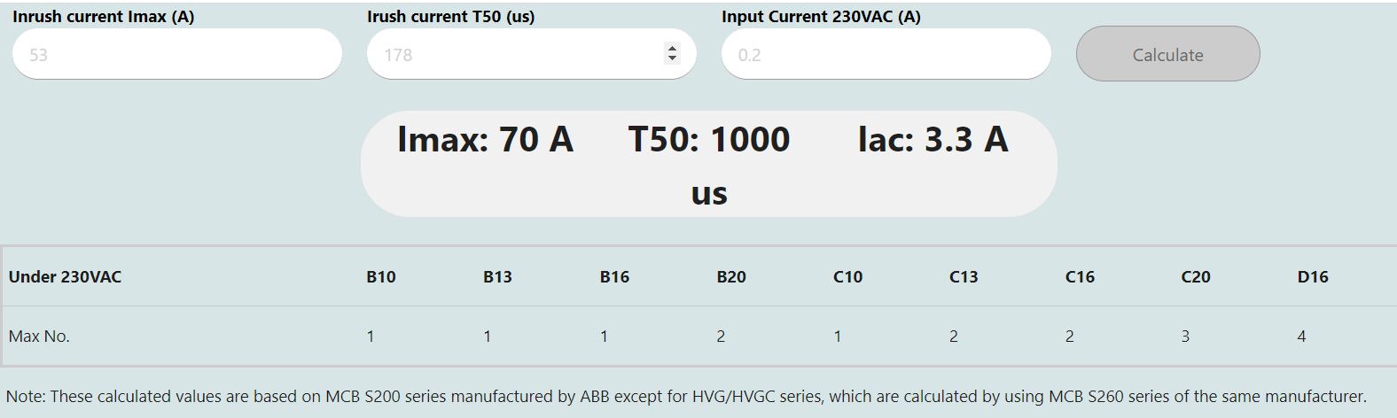
The second column indicates the maximum number of HLG-600Hs that can be connected to one circuit breaker. For example, if B10 is selected, only one HLG-600H can be connected, and if D16 is selected, four HLG-600Hs can be connected.
The following is a description of the classification of circuit breakers according to the tripping current characteristic curve:
| Classification | Tripping Current | Applicable places |
| A | (2~3)*In | For protection of very sensitive circuits such as semiconductors. |
| B | (3~5)*In | Suitable for computers, electronic equipment and residential circuit protection. |
| C | (5~10)*In | For control circuits of general device, protection of illuminating circuits with high inrush current and all other supplementary circuits. |
| D | (10~20)*In | Protection for high inrush loads like transformers, solenoid valves, etc. |
To operate with MEAN WELL power supplies, a MCB with a tripping characteristic “C” or “D” is recommended.(In : Rated Current)
Note: 1. MCB data adopts with ABB’s product, relevant data is only for reference. Different set-up may result difference.
2. Please contact MEAN WELL technicians for product without T50 information.
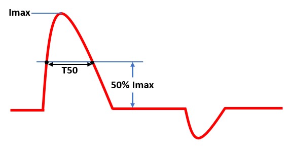
3. T50 is the time width of 50% of the inrush current value.
C: Inrush Current Limiter
For details, please refer to the following technical article " Introduction and Selection: ICL-16 Series and Circuit Breakers "
https://www.meanwell.com/newsInfo.aspx?c=5&i=765
What is the difference between 3-phase 3-wire and 3-phase 4-wire systems and how to wire?
There are two basic three-phase configurations: wye (Y) and delta (Δ). The delta connection is to connect the power sources or loads of each phase in turn to form a triangular ring. Star connection is to connect one end of the power sources or loads of each phase at one point to form a neutral point. If a neutral wire is drawn from this neutral point, the whole structure becomes a three-phase four-wire system.
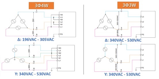
Connection of 3 3Φ4W & 3Φ3W
Comparison of 3Φ4W & 3Φ3W
| Connection | Recommended products | Application features |
| 3Φ4W | RST-5000/10000/7K5/15K | Single-phase input available |
| 3Φ3W | SHP-10K | Simple connection with AC main |
Why is that LED lamp designed with LED driver IC may sometimes cause power supply startup failure? (Output voltage gets clamped by LEDs and cannot rise to rated level)
Depending on circuit design, there could be different operational problems. See below:
- Boost mode driver IC:
The startup voltage of such driver IC is significant lower than the total LED forward voltage. For this reason, the IC will start up at very low voltage level usually about 1/2 of the power supply’s rated voltage and to meet rated power requirement, the startup current will reach 2 times the power supply’s rated current. When the power supply is unable to provide this current, the LED CC driver will not activate. - Buck mode driver IC:
If the selected power supply voltage is significantly higher than the LED forward voltage. For example, power supply provides 48V and the LED lamp only needs 24V and the power ratings are equivalent. When power supply voltage reached the LED conduction voltage, the power supply will immediately go into constant current mode. At this moment, the required power to start up the LED + driver is larger than what the power supply can provide causing malfunction of the driver circuit and the power supply to be clamped at LED forward voltage. For boost mode design, we recommend raising the startup voltage of the driver IC to be as close to the power supply voltage as possible or incorporate soft start function (see fig. 3). Wait until the power supply voltage is established before starting the driver. When selecting power supply for buck mode, the output voltage of the power supply should be as close to the LED total voltage as possible with excess power available (LED power/0.85).
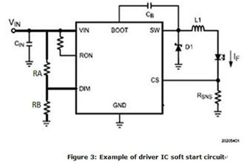
DIM PIN is the startup pin for most PWM based driver. It can also be designated as EN (Enable). DIM (or Enable) is at 0V the internal connection to SW pin will be open. When the DIM voltage reaches 1.5V (Typ), the IC will Turn ON. To set the Vstart for the DRIVER IC: Vstart = (VDIM/RB) x (RA+RB). The general rule is to set the Vstart at 5~10% higher than the total LED forward voltage.
For a particular LED lighting design, each LED strip consists of 12 LEDs connected in series (VF=3.5V), 4 strips in parallel, and each strip requires 0.7A of drive current. Based on the above conditions, how do you select a suitable power supply?
First of all, the LED power supply must be able to work in constant current mode. LED forward voltage of each strip = 3.5V X 12pcs = 42V LED lamp total current requirement = 0.7A X 4 strips in parallel = 2.8A LED power requirement = 42V X 2.8A = 117.6W LED power supply’s rated voltage/power should be greater than what is required but should be as close to the actual requirement as possible. Use 48V/150W as the basic criteria to pick LED power supply then make sure actual voltage/power usage meets constant current region and PF>0.9 specifications (117.6W/150W = 78.4% > 75%). CLG-150A-48V with output current set at 2.8A can be used in this design.
Note: Each LED production lot will fall within a VF rank (e.g.3.4~3.6V). This LED tolerance must be taken into consideration during design.
Same LED configuration as in question B1 with the exception of additional driver ICs. What is a suitable power supply unit to use?
First calculate for required voltage by combining total LED forward voltage and driver voltage drop of 2V. LED forward voltage of each strip = 3.5V x 12pcs = 42V Driver circuit required voltage = 42V + 2V = 44V LED total current requirement = 0.7A X 4 strips in parallel = 2.8A Driver circuit required wattage = 44V X 2.8A = 123.2W LED power supply's rated voltage/power should be greater than what is required but should be as close to the actual requirement as possible. Use 48V/150W as the basic criteria to pick LED power supply then make sure actual voltage/power usage meets constant current region and PF>0.9 specifications (123.2W /150W = 82.13% >75%) CLG-150A-48 with output voltage set at 44V can be used in this design
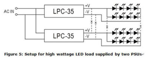
Can LED power supplies be connected in parallel?
MW LED power supply does not have parallel “current sharing” function so it is not suitable for parallel connection. For high power requirement, please select higher wattage power supply or divide LED load into smaller subsections to be powered by individual power supplies. Example of such LED configuration can be found in figure 5. As shown in fig. 5, the connection between -V of the LPC-35 units should be severed and not connected in common. On the contrary, small wattage LED loads can be connected in parallel and be powered by a single high wattage power supply. But, the ability to divide current evenly must be taken into consideration.
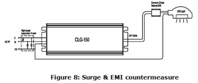
How high can MEAN WELL LED products withstand under surge test.
In the MEAN WELL LED power supply product line, the XLG optional products have the highest lightning surge withstand capability, which can reach 10KV/line 6KV/line-to-ground. If higher SURGE capability is needed, adopt ZNR (470V) or gas tube (500V) externally as alternate solution. More to that, the overall safety requirements need to be reconsidered. When multiple lamps are used, a lightning protection device (SPD: Surge protection device) can be installed to meet the requirements of regulations.
Can MW recommend the dimmers compatible to the 3 in 1 dimming circuit?
3 in 1 dimming is the most commonly applications used in LED dimming with the feature that it does not have to work with any specific dimmer. The only thing that has to be verified is that whether the dimmer (1~10V/10V PWM/resistance) is compatible with the definition advised in our specs.
What are the right product to use when intent to dimmed strip lights?
Most strip lights contain a resistor in series, as the result, constant voltage LED driver must be used in this kind of application. We recommend to choose dimmable constant voltage LED drivers such as, PWM/IDLV/ODLV.
How can we learn how many units of the model with 3 in 1 dimming can be controlled by one dimming device?
3 in 1 dimming circuit would drain 0.1mA per model. Dividing the rated current of the dimmer by the 0.1mA, and we could know how many units can be controlled by one dimming device. For resistance dimming applications, resistance for 100% dimming output would be 100K ohm divided number of models.
Can we use LED CC model as a charger?
MW has several charger products, and we suggest choosing them first. Chargers would be more suitable since they are designed for charging applications. Safety & Approvals should be taken into account. If you really cannot find a proper model in our chargers series, our LED CC models can be used as charger. Please choose suitable products after confirming the current and voltage specification on the datasheet of the battery.
There are so many MW dimming products. How can I make a choice? What are the pros and cons?
First, you have to know your Led lamp specification in order to screen out a suitable Led driver range (Wattage, Voltage, Max Current CC or CV). From those ranges, further check a compatible dimming function. Hereunder is a table to show you the pros and cons of Dimming Function you can find in MW's catalogue. 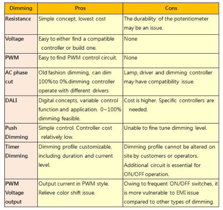
Can I use MW LED drivers at full load continuously? Most of the AC/DC power supply are suggested to use at 70% load.
LED Drivers are recommended operate at full load as long as it observes the working temperature specified in the datasheet, which means Tc measurement results should be equal to or less than the stated Tc in the datasheet. 5 years warranty complies as long as drivers operate within working Temp and Tc. Limit as well.
Can I wire LDD or LDH in parallel or series?
LDD/LDH series comprises switching components; series or parallel connection will damage these switching components.
How long can I extend DC cable of the driver?
Owing to line (voltage)-drop, we suggest the extension made from AC cable. In case DC cable extension is necessary, please consider Line-Drop leading to insufficient Vf so that the LED model or lamp may fail to switch ON. Moreover, EMC performance and characteristic may also be affected by DC cable extension.
Why is that during LED power supply operation the LED sometimes varies in brightness or flickers?
MW developed many power supplies series specifically for LED application. Single stage PFC was used in such developments due to low cost. This topology has the following restrictions:
- AC fluctuation
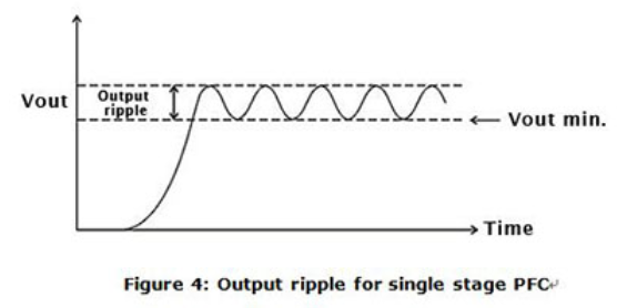
This topology does not use input bulk capacitor. For this reason, in areas with low AC quality, output voltage and current may become unstable causing variation in LED brightness. If the input AC voltage is stable then this problem will not occur. - Output ripple
This is also caused by lack of input bulk capacitor. As compared to power supplies using dual stage PFC, the ripple will be significantly larger (see Figure 4). There could be instances where the low end of the ripple may be too low for the driver IC to operate properly and the LEDs will start to flicker. To solve this type of problem, the output voltage can be adjusted higher so the low end is higher than the driver’s minimum working voltage. Or simply select a PSU with higher rated voltage. - Current harmouics
Single stage PFC power supplies are optimize for constant current drive. Using these supplies as constant voltage sources (such as application including cascading a constant current driver IC), the harmonics might be worsen in this case. When operating in areas with unstable utility voltage or with driver IC, we highly recommend using general application types as found in table 1. Avoid using single stage PFC if possible, or contact MEANWELL.
What's the reason that dimming is not working with MEAN WELL dimmable LED driver.
First of all. Determine the driving method of LED lamp. If the lamp is driven by constant current, forward current shall be within specification. On the contract, if it's driven by constant voltage, then user must check if they are using the right product to dim the LED lamp, such as PWM series or model with PWM output in XLN-60/XLC-60 series.