
If you have questions on MEAN WELL’s products, please read the FAQ first. If the listed answers still cannot solve your problems, please contact our local distributors , they should reply to you as soon as received your request.
As a dedicated manufacturer of standard power supplies, MEAN WELL provides a wide variety of power supplies to meet different demands from the markets. However, selecting the right products relies heavily on the correct electrical characteristics and specification, we listed the frequently asked questions for your reference.
Functionality Aspect
Notes on choosing a switching power supply?
- To increase the reliability of the S.P.S., we suggest users choose a unit that has a rating of 30% more power than actual need. For example, if the system needs a 100W source, we suggest that users choose a S.P.S. with 130W of output power or more. By doing this, you can effectively boost the reliability of the S.P.S. in your system.
- We also need to consider about ambient temperature of the S.P.S. and whether there is additional device for dissipating the heat. If the S.P.S. is working in a high temperature environment, we need to make some derating to the output power. The derating curve of "ambient temperature" versus "output power" can be found on our spec sheets.
- Choosing functions based on your application:
- Protection function: Over Voltage Protection (OVP), Over Temperature Protection (OVP), Over Load Protection (OLP), and etc.
- Application function: Signaling Function (Power Good, Power Fail), Remote Control, Remote Sensing, and etc.
- Special function: Power Factor Correction (PFC), Uninterruptible Power Supply (UPS) function.
4. Make sure that the model qualifies for the safety standards and EMC regulations you need.
Can MEAN WELL's power supply be used in the range of 45Hz ~ 440Hz? If YES, what will happen?
MEAN WELL's power supply can be used within this frequency range. But if the frequency is too low, the efficiency will also be lower. For example, when a SP-200-24 is operated under 230VAC and rated load, if the frequency of AC input is 60 Hz, the efficiency is around 84%; however, if the frequency of AC input reduces to 50 Hz, the efficiency will be around 83.8%. If the frequency is too high, the power factor of the S.P.S. with PFC (power factor correction) function will reduce and this also will cause higher leakage current. For example, when a SP-200-24 is operated under 230VAC and rated load, if the frequency of AC input is 60 Hz, the power factor is 0.93 and the leakage current is around 0.7mA; however, if the frequency of AC input increase to 440 Hz, the power factor will decrease to 0.75 and the leakage current will rise to around 4.3mA.
What is minimum load requirement and how can I read it from the spec?
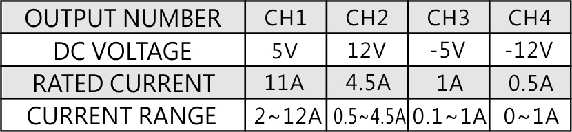
There are some minimum-load requirements on MEAN WELL's multi-output power supplies. Please read the specification first before connecting to the load. In order to allow the power supply to work properly, a minimum load for each output is required, or else, the output voltage level will be unstable or outer tolerance range. Please refer to “Current range” in the specification as shown in the table below: Channel 1 requires a 2A minimum-load; channel 2 requires 0.5A; Channel 3 requires 0.1A ; Channel 4 does not need any minimum-load.
Why did the power supply shuts down during operation and after turning it off, I can restart the power supply again?
In general there are two circumstances that will cause the power supply to shut down. The first one is the activation of the over-load-protection (OLP). To deal with this situation, we suggest increasing the rating of the output power or modifying the OLP point. The second one is the activation of over-temperature protection (OTP) when the internal temperature reaches the pre-set value. All of these conditions will let the S.P.S. enter protection mode and shut down. After these conditions are removed, the S.P.S. will be back to normal.
What is the control mechanism for cooling fans?
Cooling fans have a relatively shorter lifetime (typical MTTF, Mean Time To Failure, of around 5000-100000 hours) compared with other components of power supply. As a result, changing operating method of the fans can extend the operation hours. The most common control schemes are shown as below:
- Temperature control: if the internal temperature of a power supply, detected by a temperature sensor, is over the threshold, the fan will start working at full speed, whereas, if the internal temperature is less than the set threshold, the fan will stop working or run at half speed. In addition, cooling fans in some power supplies are controlled by a non-linear control method whereby fan speed can be changed with different internal temperatures synchronously.
- Load control: if the loading of a power supply is over the threshold, the fan will start working at full speed, whereas, if the loading is less than the set threshold, the fan will stop working or run at half speed.
What is "Inrush Current"? What will we notice?
At input side, there will be (1/2 ~1 cycle, ex. 1/120 ~ 1/60 seconds for 60 Hz AC source) large pulse current (20~100A based on the design of S.P.S.) at the moment of power on and then back to normal rating. This "Inrush Current" will appear every time you turn on the power. Although it will not damage the power supply, we suggest not turning the power supply ON/OFF very quickly within a short time. Besides, if there are several power supplies turning on at the same time, the dispatching system of AC source may shut off and go into protection mode because of the huge inrush current. It is suggested that these power supplies start up one by one or use the remote control function of S.P.S. to turn them on/off.
What is PFC?
Power Factor Correction or PFC is to improve the ratio of apparent power to real power. The power factor is around 0.4~0.6 in non-PFC models. In models with PFC circuit, the power factor can reach above 0.95. The calculation formulas are as follows: Apparent Power=Input Voltage x Input Current (VA), Real Power= Input Voltage x Input Current x Power Factor (W).
From the point of view of environment friendly, the power plant needs to generate a power which is higher than apparent power in order to steadily provide electricity. The real usage of electricity is defined by real power. Assuming the power factor is 0.5, the power plant needs to produce more than 2WVA to satisfy 1W real power usage. On the contrary, if the power factor is 0.95, the power plant only needs to generate more than 1.06VA to provide 1W real power, It will be more effective in energy saving with PFC function.
Active PFC topologies can be divided into single-stage active PFC and two-stage active PFC, the difference is show as in the table below.
| PFC topology | Advantage | Disadvantage | Limitation |
| Single-stage active PFC |
Low cost Simple schematic High efficiency in small watt application |
Huge Ripple complex feedback control |
1.Zero “hold up time”. The output is affected by the AC input directly. 2.Huge ripple current results in lower LED life cycle.(drive the LED directly) 3.Low dynamic responds, easily affected by load. |
| Two-stage active PFC |
High efficiency Higher PF Easy feedback control High adoptive against load condition |
Higher cost Complex schematic |
Suitable for all kinds use |
What is the difference between -V and COM which are marked on the output side?
COM (COMMON) means common ground. Please see below:
Single output: Positive pole (+V), Negative pole (-V)
Multiple output (Common ground): Positive pole (+V1, +V2,.), Negative pole (COM)
In MEAN WELL's catalog, we see AC and DC at input, what is it all about?
Due to different circuit designs, MEAN WELL power supply's input consists of three types as below:
(VAC≒VDC)
a.85~264VAC;120~370VDC
b.176~264VAC;250~370VDC
c.85~132VAC/176~264VAC by Switch; 250~370VDC
- In a and b inputs models, power supply can work properly no matter under AC or DC input. Some models need correct connection of input poles, positive pole connects to AC/L; negative pole connects to AC/N. Others may require opposite connection, positive pole to AC/N; negative pole to AC/L. If customers make a wrong connection, the power supply will not be broken. You can just reverse the input poles and power supply will still work.
- In c input models, please make sure that you switch the 115/230V input correctly. If the switch is on the 115V side and the real input is 230V, the power supply will be damaged.
What is MTBF? Is it distinct from Life Cycle? What is DMTBF?
MTBF (Mean Time Between Failure) and Life Cycle are both indicators of reliability. MTBF can be calculated by two different methodologies, which are “part count” and “stress analysis”. The regulations, MIL-HDBK-217F Notice 2 and TELCORDIA SR/TR-332(Bellcore) are commonly used to calculate MTBF. MIL-HDBK-217F is a United States military standard, and TELCORDIA SR/TR-332(Bellcore) is a commercial regulation. MEAN WELL utilize MIL-HDBK-217F(Stress Analysis) as the core of MTBF. The exact meaning of MTBF is, after continuously using the power supply for a certain amount of time, the average time that the probability of proper operation is down to 36.8%(e-1=0.368). Currently MEAN WELL is adopting MIL-HDBK-217F, forecasting the expected reliability through Stress Analysis (excluding fans); this MTBF means the probability of the product can continue the normal work after working continuously up to the calculated MTBF time is 36.8% (e-1=0.368). If the power supply is continuously used at double the MTBF time, the probability of proper operation becomes 13.5%(e-2=0.135). Life Cycle is found by using the temperature rise of electrolytic capacitors under maximum operating temperature to estimate the approximate life of the power supply. For example, RSP-750-12 MTBF=109.1K hours(25°C); electrolytic capacitor C110 Life Cycle=213K hours (Ta=50℃)
DMTBF(Demonstration Mean Time Between Failure) is a way of evaluate MTBF。Please refer to the following equation for MTBF calculation.


MTBF:Mean Time Between Failure
X2:Can be found in chi-square distribution
N:Number of sampling
AF:Acceleration factor, which can be derived from acceleration factor equation.
Ae=0.6
K(Boltzmann Constant)=(eV/k)
T1:Rated temperature of specification. Note: Kelvin will be the unit use for calculation
T2:The temperature that is used in the meaning of acceleration, and the chosen temperature could not result in physical change in materials. Note: Kelvin will be the unit use for calculation.
What is power good and power fail signals and how can use it?
Some power supplies provide a "Power Good" signal when they are turned on, and send out a " Power Fail" signal when they are turned off. This is usually used for monitoring and controlling purpose.
Power Good: after the output of a power supply reaches 90% rated voltage, an TTL signal (about 5V) will be sent out within the next 10-500ms.
Power Fail: before the output of a power supply is less than 90% rated voltage, the power-good signal will be turned off at least 1ms in advance.

I have an TN-1500 inverter. Why the LED indication of AC IN is not lit after mains input has been applied?
According to the mains voltage of different countries, the output of TN-1500 inverter 110VAC version can be altered to 100/110/115/120VAC. In the same way, TN-1500 inverter 220VAC version can be changed to 200/220/230/240VAC as well. When the inverter is set in UPS mode and the mains voltage fluctuates over ?5% of the set AC output voltage, the inverter will shift its power source from the city power to battery to remain the accuracy of the AC output Voltage. Meanwhile, the AC IN indicator on the front panel of the inverter will be turned off.
What are the protection forms of overload/overcurrent?
When current drawn exceeds the rating of the PSU, the protection circuit will be triggered to protect the unit against overload/overcurrent.
Protections of overload/overcurrent can be divided into several forms:
(1)FOLDBACK CURRENT LIMITING
Output current decreases about 20% of rated current, shown as curve (a) in the figure below.
(2)CONSTANT CURRENT LIMITING
Output current remains at a constant level and within the specified range while the output voltage drops to a lower level, shown as curve (b) in the figure below.
(3)OVER POWER LIMITING
Output power remains constant. As output load increases, output voltage decreases in proportion, shown as curve (c) in the figure below.
(4)HICCUP CURRENT LIMITING
Output voltage and current keep pulsing ON and OFF repeatedly when protection is activated. The unit automatically recovers when faulty condition is removed.
(5)SHUT OFF
Output voltage and current are cut off when output load reaches protection range.
NOTE: Protection mode of some of the products combines with different types of the forms mentioned, such as constant current limiting + shut down.

Recover method:
(1)Auto Recovery: PSU recovers automatically after faulty condition is removed.
(2)Re-power on: PSU restarts by manual AC re-power on after faulty condition is removed.
Note:Please do not operate PSU in overcurrent or short-circuit condition for a long period of time to prevent a shorten lifespan or damaging the PSU.
What is Ripple & Noise? How to measure it?
It is the small unwanted residual periodic variation of the direct current (DC) output of a power supply which has been derived from an alternating current (AC) source. The wave form is shown as figure below.

There are two AC contents, also known as Ripple and Noise (R&N), on the DC output. The first one, coming from sine wave rectification, is at a low frequency which is 2 times of the input frequency; the second one is at high frequency which is from the switching frequency. For measuring high frequency noise, configurations of an oscilloscope with a bandwidth of 20MHz, a scope probe with shortest ground wire possible, and add 0.1uF and 47uF capacitors in parallel with test point for filtering out noise interference are requires to be made.

What is Withstand Voltage?How to measure it?
Indicates Hi-Pot Test or Electric Strength Test. The input should be shorted together as well as the output before test. The test will proceed under particular loop, such as I/P-O/P, I/P-FG and O/P-FG with certain high voltage value for 1 minute. (The typical leakage current is 25mA when testing with AC)
.jpg)
- Hi-Pot Test is a way to ensure if the isolation between primary to secondary is done properly, preventing damaging to S.P.S. when facing high voltage between input and output. The test voltage should be gradually increased from 0V to preset level and remains at preset level for 60 seconds with raise time greater than 1 second. In mass production, the test period could be reduced to 1 second. If the leakage current flowing through the isolation material increases rapidly when applying test voltage, it indicates ineffectiveness of isolation (dielectricbreakdown). Corona effect/discharge or transient electrical arc is not considered as failure.
- When AC test voltage is applied, Y capacitors are the main cause of leakage current. A 4.7nF capacitor can cause leakage current of 5mA. According to regulations of UL-554, the Y capacitors should be removed for Hi-Pot test, which is not practical for mass production. The only solution is to increase the leakage current setting, typically 25mA, of test instrument. Presently, the criteria of leakage current are not defined in safety regulations.
- According to regulations of IEC60950-1, DC test voltage can be substituted when there are bridging capacitors coupled between primary and econdary circuits, so as to solve the problem of leakage current.
How does MEAN WELL define switching time of 1ms(BIC-2200)?
The switching time is the time period which current flow from one direction to another, under 5% of Vo variation. Please refer to the figures below for definition and actual waveform.

Test Result:
| MODE | BIDIRECTION SWITCH TIME | Result |
| AC to DC Direction | 1ms | 888 us |
| DC to AC Direction | 1ms | 681 us |


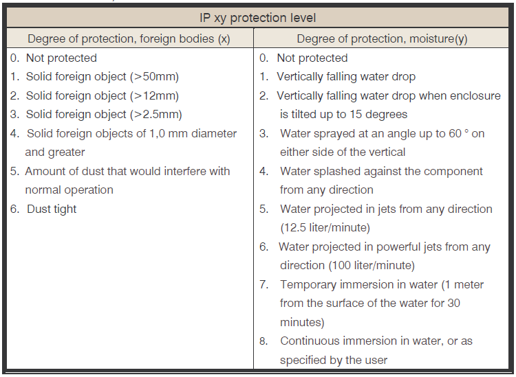
What is the definition of IP (Ingress Protection) ratings? And what is MeanWell’s IP68 definition.
MEAN WELL has incorporated dust proofing and water proofing into majority of its LED power supply design. Mainly based on the international standard IEC60529, detailed descriptions can be found in the following table:
(Note: PSUs with IP64 rating or above are suitable for indoor or outdoor applications in sheltered locations)
*IP64-IP66 level and IP67 with potentiometer products are suitable for damp indoor or sheltered outdoor environment. For actual installation limitations, please refer to the corresponding IP level tests.
*All products cannot be continuously submerged in water.
*The definition of IP68 by MEAN WELL: Immerse a unit under test in 1 meter below the surface of the water, tested with a dynamic condition where 12 hour AC on; 12 hour AC off.
Test duration: 1 month.
How to select a suitable MEAN WELL LED power supply?
- Select suitable wattage based on customer's system requirements and application methods. Must also take excess power and driving method into consideration.
- For selection key points when using MW power supply to “directly” drive LED lamp refer to LED configuration and installation notes.
- For selection key points when using MW power supply in combination with LED driver IC to achieve high precision current control refer to LED configuration and installation notes.
- Based on LED power supply's operating environment select suitable IP level and mechanical type (metal enclosure, plastic enclosure, and open frame PCB) for that environment.
- Is PFC function required or not? Single stage PFC is only suitable for LED load. Dual stage PFC is suitable for general applications.
- If LED system is based on direct drive, units with adjustable voltage and current should be considered for flexibility in changing voltage/current levels. Dimming function may also come in handy when LED brightness control is preferred.
and two stage power supply.
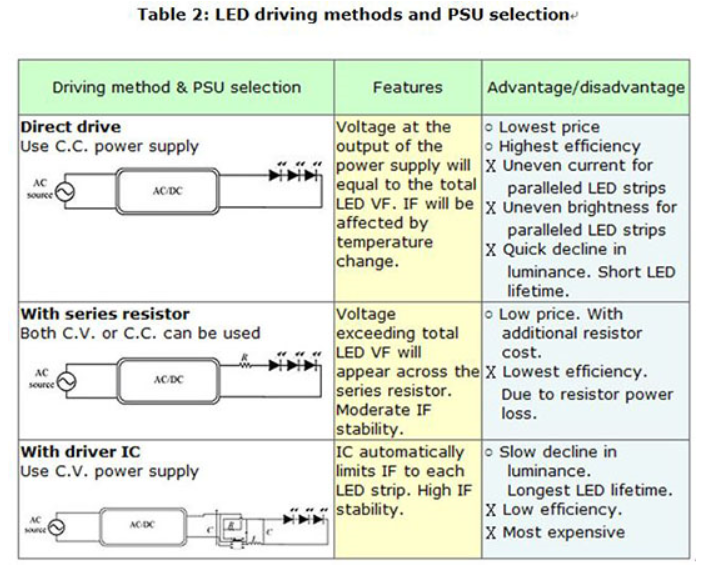
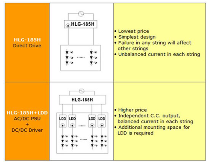
What are the most common LED driving methods? What are its advantages and disadvantages?
What to consider when selecting LED power supply?
- Lighting system designed to work in direct drive mode
- The combined LED forward voltage range (upper and lower) must fall within LED power supply’s constant current voltage range. For example, the LED Vf spec is 3.4~3.6V, when 6 are connected in series the combined Vf will be 20.4~21.6V. In this case, a 24V unit must be selected with constant current region of 18~24V.Ø
- For models with active PFC and system PF requirement is >0.9, load usage must be higher than as specified in the PFC spec. Relationship between PF and output load can be found in figure 1. The typical requirement is 75% load or above. Double check the spec for the model you are using to confirm actual requirement.
- In areas with unstable AC voltage such as heavy industrial zone or generator supply utility, please select general usage LED series from table 1.
- Lighting system designed to work with driver IC
- The start up voltage of driver IC should be as close to the power supply rated voltage as possible.
- Driver IC needs stable voltage to function properly. So, it is highly recommended to use general usage series from table 1.
- For models with active PFC and system PF requirement is >0.9, load usage must be higher than as specified in the PFC spec. Relationship between PF and output load can be found in figure 1. The typical requirement is 75% load or above.
- Double check the spec for the model you are using to confirm actual requirement. When using driver IC, possible system EMI issue could arise. After completing lighting system design, EMI must be double checked.

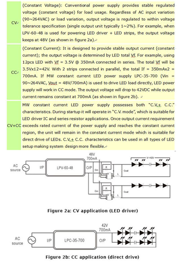
What are CV, CC, and CV+CC which are often mentioned in LED power supply specification?
What is the concept of constant power design? What's the difference when comparing to constant current design?
The driving method of constant power LED driver is same as the principle of constant current mode drivers. Except that, the maximum power of a general constant current LED driver will only be fixed at a single output voltage and output current. The constant power LED driver adopts a wide range of output voltage and current Design. Wide range of fixed maximum output power range, provide flexible and efficient LED voltage and current configuration, optimized size and inventory. As shown in the figure, the output voltage and current in between 232V/2800mA and 185.6V/3500mA can produce maximum output power of 650W.

Does MW LED power supply allow adjustment of output voltage and current levels?
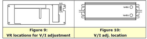
LED power supply comparison table to see which MW LED power supply allows for V/I adjustments. A suitable unit can be picked based on the type of adjustment required. For the allowed adjustment range, please refer to the spec sheet. Tuning of the voltage and current levels can be done through the built-in VRs/potentiometers. PLN/ELN requires removal of the top cover in order to access the internal SVR1 and SVR2, see figure 9 for VR locations. For other series, the VRs can be accessed through IoADJ and VoADJ holes after rubber stopper removal. After adjustments have been made, please make sure rate power is not exceeded and the rubber stoppers are properly reassembled.
Can MEAN WELL IP67 products exposed to open field?
Please check if the IP67 is equipped with ADJ function or not. Due to the mechanism design of potentiometer for IP67 products, the protections are not as perfect as BLANK type. Therefore, please choose BLNK version when application is not sheltered.
To design a LED street lamp, what solution can MEAN WELL offer?
What is the main difference between 1~10V dimming and 0~10V dimming regarding applications?
With 1~10V dimming, the lighting unit can be dimmed down to 10%; with 0~10V dimming, it can be dim down to 0%, or say, dim to “off”.
What is the current accuracy of LED SPS?
For LED SPS output current accuracy, please refer to product specification. For CC model, “CURRENT ACCURACY” is listed in SPECIFICATION section. For CC+CV model, please reference the OVER CURRENT range in PROTECTION of the SPECIFICATION section.
What is the difference between Single Stage and Two Stage Power Supply?
There are 2 types of Power Factor Correction circuits; one is Single Stage and the other is Two Stage. Single stage power supply combines functions of power factor correction and converter in one circuit but two stage use two separate circuits. Compared to Single Stage, Two Stage design is more complex and costly but the immunity performance of Two Stage PSU against AC mains is much better than that of Single Stage PSU; in addition, Two Stage manifests better ripple noises performance on output. Owing to that Single Stage is only suitable for fields with quality AC mains but Two Stage can be used in serious circumstance for LED drivers or as industrial switching power supplies.
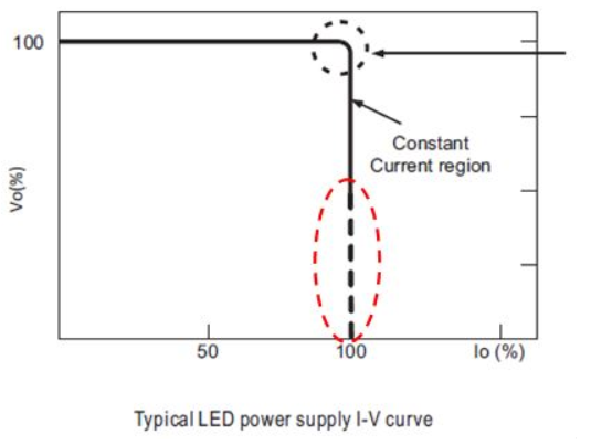
How am I supposed to read the LED V-I dotted line & tolerance definition in the specification?
Mean Well’s LED product specification normally exhibits V-I characteristics. Per the characteristics, there are generally two types of drivers, “CC” type and “CC+CV” type. “CC” type of driver is suitable only for LED applications whereas “CC+CV” for either LED applications or general switching power supply applications. The section that is not suitable for LED applications are represented by dotted line, and based on the protection procedures it can be categorized into hiccup mode and constant current mode; in this section, the tolerance of current is not defined but only the characteristic of current is displayed. If customers attempt not to see a very high current under short circuit condition, those models with hiccup mode for this section can be selected; if there are applications with motors or capacitive load, those with constant current can be chosen.
When the MTBF of MEAN WELL product is shorter than competitor’s, does it mean that the quality of MEAN WELL is lower than other brands?
The answer is NO. The calculation of MTBF contain many variations, the version of MTBF, stress of component and the number of components can make difference. Not like other OEM/ODM companies, MEAN WELL sells standard power supply with our own brand, so the MTBF parameter is not able to customized one by one according to the application. Therefore, MEAN WELL still seek for improvement and MEAN WELL re-examined the MTBF parameters of TELCORDIA SR/TR-332(Bellcore) and implemented an optimization. MEAN WELL reviewing the supplier quality policy and accompanying with IQC/OQC/FQC…etc., all the ways to after-sales service, ensure preventing recurrence, which not only brings the quality of MEAN WELL products to another level, but it also changes the status of the quality factor πQ of the MTBF equation as shown in Table 1 according to TELCORDIA SR/TR-332(Bellcore) regulation. Leading the MTBF reading can be optimized from Level 0~I to Level I~II. For more detail, please refer to https://www.meanwell.com/newsInfo.aspx?c=5&i=1026.
Although MTBF can be one of the parameter that represent quality, but it’s not the only parameter what we should consider when choosing a power supply. From Brand, price, lead time, service to warranty, all of them shall be well considered together.
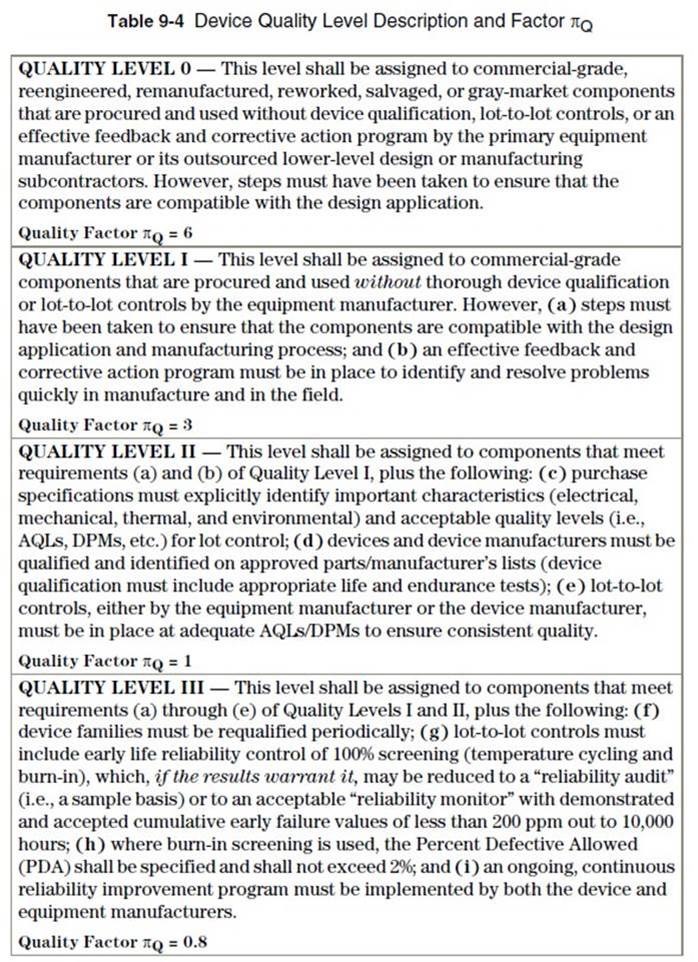
Table 1. Device Quality Level Description and Factor of TELCORDIA SR/TR-332(Bellcore)